
DC-DC Converter: Types, How It Works & Selection Guide
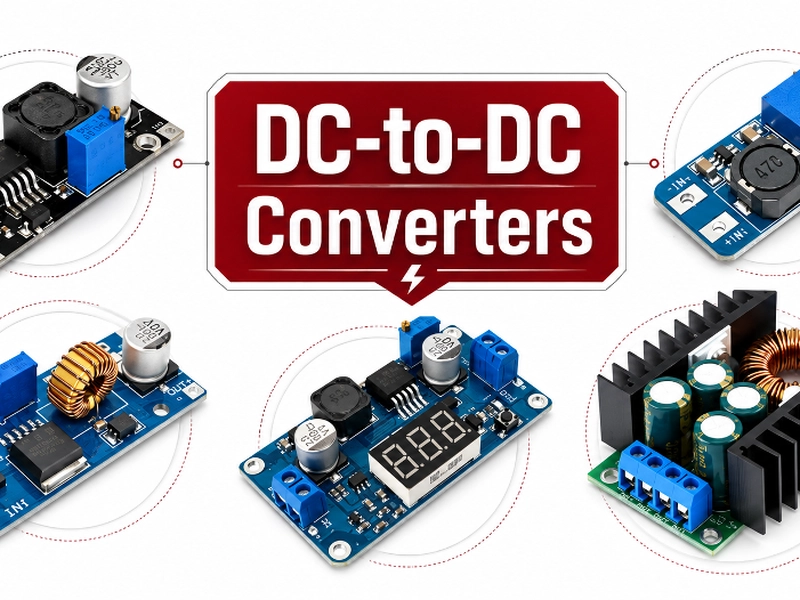
Every electronic system needs the right voltage in the right place. The incoming supply rarely matches what a circuit actually needs.
A 24V industrial rail has to feed 5V logic. A 48V telecom bus has to power 12V fan controllers. A 3.7V battery has to hold a steady 5V rail as it discharges.
The component responsible for all of this is the DC-DC converter, one of the most widely stocked categories under board mount power supplies.
This guide covers what a DC-DC converter is and how it works. It also covers the topologies you will see on a datasheet and the specifications that matter most when selecting a module for a real design.
In most cases that means stepping the voltage up, down, or both. But an isolated converter can also hold the same nominal voltage on both sides purely to provide galvanic isolation.
Not every DC-DC module offers a regulated output, either. Some isolated modules, particularly lower-cost ones, deliver an unregulated or semi-regulated output instead.
These parts range widely in form factor. Some are a handful of components built around a single switching IC on a PCB.
Others come as fully encapsulated modules, often called power bricks, that an engineer treats as a single drop-in part.
So both are DC-DC converters in the functional sense. The difference is packaging and integration level, not the underlying job the part performs.
[Photo placeholder] A product photo of a board-mount DC-DC converter module (DIP, SIP, or brick package) belongs here. Pull one from Fly-Wing’s own DC-DC converter listings rather than a stock or competitor image, since those photos are already licensed for Fly-Wing’s own use.
It is worth drawing one boundary here. Linear regulators and LDOs also convert one DC voltage into another.
In component catalogs and everyday power electronics discussion, though, engineers normally reserve the term DC-DC converter for switching designs. LDOs and linear regulators get their own category.
For a closer look at that boundary, see our LDO vs buck converter comparison. Our linear vs switching regulator guide covers the full picture.
How Does a DC-DC Converter Work?
Switching DC-DC converters share a common strategy: store energy briefly, then release it at the new voltage.
A buck converter shows this principle most clearly, so it is worth walking through step by step before looking at the other topologies.
The Switching Cycle
A buck converter’s power switch turns on and off at high frequency, while an inductor and capacitor smooth the resulting pulses into a steady output.
The ratio of on-time to total switching period, known as the duty cycle, sets the relationship between input and output voltage. For an ideal buck converter:
VOUT = VIN × D
So a 24V input running at a 20 percent duty cycle produces an ideal output of 4.8V. See TI’s buck converter design note for the full derivation.
During the switch’s on-time, current flows through the inductor and energy stores in its magnetic field.
During the off-time, that stored energy releases into the output capacitor and load.
A feedback loop continuously compares the output voltage against a reference. It then adjusts the duty cycle to keep the output steady as input voltage or load current changes.